• Wuhan Mingyang Technology Co., Ltd
    Global Power Solution Engineer
    Stable quality, on-time delivery, reliable long-term partner.
  • Wuhan Mingyang Technology Co., Ltd
    Gulf Electrical Engineering Se
    Professional technology and perfect after-sales service.
  • Wuhan Mingyang Technology Co., Ltd
    International Power Research L
    Customized solution meets our project requirements perfectly.
  • Wuhan Mingyang Technology Co., Ltd
    South America Electric Power P
    Professional team, good communication and stable supply.
Contact Person : Emma Zhang
Phone Number : +86 18627175510
WhatsApp : +8618627175510

3‑Phase Microcomputer Relay Protection Test Set Secondary Injection Tester For Substation Protection Relay Calibration

Place of Origin China Mainland
Brand Name MINGYANG
Model Number MY-702
Minimum Order Quantity 1
Price 3200usd
Packaging Details carton
Delivery Time 1 week
Payment Terms L/C,D/A,D/P,T/T,Western Union
Supply Ability 1000pcs/month
Product Details
Type Testing Machine Voltage Other
Accuracy Class High Accuracy Protection Class IP55
Place Of Origin China Customized Support OEM, ODM, OBM
Maximum Output Load Voltage 20V Phase Voltage/line Voltage Output Power 70VA/140VA
Maximum Output Power Of Phase Current 450VA Harmonic Frequency 0-20 Times (online) 0-6 Times (single Machine)
Output Accuracy 0.2 Level
Highlight

Three Phase relay protection tester

,

High Precision relay protection tester

,

Multi Output 3 phase relay tester

Leave a Message
Product Description

3‑Phase Microcomputer Relay Protection Test Set Secondary Injection Tester For Substation Protection Relay Calibration

Product Description
This innovative Relay Protection Device Tester embodies the cutting-edge standards set forth by the Ministry of Electric Power in the DL/T624-1997 technical conditions for microcomputer-type relay protection test devices. Drawing from extensive user feedback and synthesizing the strengths and weaknesses of similar products, this state-of-the-art tester leverages modern microelectronics technology to deliver a compact, miniaturized microcomputer relay protection solution. Experience a new era in relay protection testing with this advanced device.
Product Alias
Microcomputer relay protection tester / 3‑phase relay protection test set / Secondary injection test kit / Secondary injection tester / Protective relay test set / Relay calibrator / Substation relay test instrument / Universal relay protection tester / Digital relay test system
Features
1.Featuring a 6.4-inch TFT true-color LCD display and trackball operation, it enables all functions without external keyboard or mouse, with an intuitive English interface.
2.The system supports three testing modes: manual, semi-automatic, and fully automatic.
3.In automatic mode, it performs multiple rounds of testing and data recording without human intervention.
4.It includes 10 digital inputs and 8 digital outputs, compatible with both air contacts and 0-250V potentiometric contacts, allowing easy connection to protection device signals for automated testing linkage.
Product Parameters
AC current output
1. AC current output: Output accuracy: 0.2 level
2. Phase current output (effective value): 0-40A
3. Three parallel current output (effective value): 0-120A
4. Long term allowable operating value (effective value) of phase current: 10A
5. Maximum output power of phase current: 450VA
6. Maximum output power at maximum output of triple current: 900VA
7. Allowable working time for maximum output of triple current: 10s
8. Frequency range (fundamental) 0-1000Hz (online) 0-300Hz (standalone) Harmonic order 0-20 times (online) 0-6 times (single machine)
DC current output
1. Output accuracy: Level 0.5
2. Current output: 0~± 10A per phase, 0~± 30A per triple junction
3. Maximum output load voltage: 20V
AC voltage output
1. Output accuracy: 0.2 level
2. Phase voltage output (effective value): 0-120V
3. Line voltage output (effective value): 0-240V
4. Phase voltage/line voltage output power: 80VA/100VA
5. Frequency range (fundamental): 0-1000Hz (online) 0-300Hz (standalone)
6. Harmonic frequency: 0-20 times (online) 0-6 times (single machine)
DC voltage output
1. Output accuracy: Level 0.5
2. Phase voltage output amplitude: 0 to ± 160V
3. Line voltage output amplitude: 0 to ± 320V
4. Phase voltage/line voltage output power: 70VA/140VA
Measurement of switch quantity and time
1. Switching input with 8 empty contacts: 1-20mA, 24V
2. Potential contact connection: "0": 0~+6V; “1”:+11 V~ +250V
3. Switching output 4 pairs DC: 220V/0.2A; AC:220V/0.5A
4. Time measurement range: 0.1ms to 9999s, measurement accuracy: 0.1ms
Application Scenarios
3‑Phase Microcomputer Relay Protection Test Set Secondary Injection Tester For Substation Protection Relay Calibration
FAQ
Question 1: No voltage and current output after starting the device
Customer: After power‑on and parameter configuration, the instrument shows normal interface display, but there is no voltage or current output. What may cause this fault?
Manufacturer: This problem is common in field tests, please troubleshoot step‑by‑step. First, confirm whether the test mode is correctly selected and check if the output enable button on the software panel has been activated. Second, inspect the external test wiring; verify that the voltage and current output terminals are securely connected to the protection device under test, and check for open‑circuit cables. In addition, check whether over‑current or over‑voltage protection is triggered, which will lock the output channel. If the above operations cannot solve the problem, please contact us promptly and do not disassemble the equipment by yourself.
Question 2: Binary input channel cannot capture protection action signal
Customer: We have connected the action contact of the protective relay to the binary input terminal. However, the instrument cannot detect the tripping or closing action feedback signal during test execution. How to resolve this issue?
Manufacturer: This fault is usually caused by wrong wiring, incorrect contact type setting or signal level mismatch. Please take the following measures: First, double‑check the binary input wiring and confirm whether dry‑contact or wet‑contact mode is selected on software according to actual relay contact type. Second, check the action state of the relay itself to confirm whether the contact can conduct normally after protection tripping. Third, verify that the common COM terminal of binary input is correctly connected. If the protective device itself has output abnormality, it will also lead to no feedback signal; under such circumstances, please inspect the tested relay device first.
Question 3: Fan fails to run; device over‑temperature protection is triggered under high‑current output
Customer: When outputting large current for a long time, the internal fan stops working, and the over‑temperature alarm pops‑up on screen. Is the internal power module burnt out?
Manufacturer: Do not panic. In most cases, this is protective locking rather than permanent hardware damage. Continuous high‑current output and poor heat dissipation will activate thermal protection of power amplifier module. The correct handling procedure is: disconnect the AC power supply, allow the device to stand for about 30 minutes for full cooling. Re‑power the instrument, click fault reset function on software panel, then restart the test. Avoid long‑time full‑current continuous operation. If the alarm still exists after cooling and reset, please contact our technical support and do not open the cabinet privately.
Question 4: Main unit suffers frequent automatic reset and tripping during field test
Customer: During substation secondary‑injection test, the relay test set resets accidentally occasionally, the running test procedure is interrupted and test data is lost. Is there any way to avoid this situation?
Manufacturer: There are three main causes for unexpected reset: input power supply fluctuation, strong external electromagnetic interference and unreliable grounding of main unit. It is recommended to adopt an independent power source with sufficient capacity on‑site and avoid sharing the same circuit with large‑power equipment such as high‑voltage test devices. The main unit must be reliably grounded, and grounding electrode shall be buried in damp soil. Place the instrument as far away as possible from high‑voltage equipment and interference sources. If frequent resets still occur after troubleshooting, please provide us with on‑site wiring diagram and description of fault phenomena; we will dispatch technical personnel to provide remote guidance.
Question 5: Precautions for Transportation, Handling, and Wiring
Customer: This test system contains power amplifier module, multiple output terminals and signal interfaces. What special precautions should we follow for on‑site operation, installation and transportation?
Manufacturer: Please comply with these key requirements: First, this instrument is used for secondary injection test of power system protection devices. Operators shall possess relevant high‑voltage test qualifications; at least two‑person operation is required and strictly abide by local electric power safety regulations. Second, strictly distinguish voltage output, current output, binary input and binary output terminals. Wrong wiring may burn out both the tester and the tested protection relay; double‑check all wiring after connection completion. Third, avoid violent impact and drop during transportation; protect the touch screen and internal power amplifier components from collision. Fourth, before test, confirm the parameter setting matches the setting value of the protection device under test to prevent mis‑operation. Fifth, store the equipment in dry and ventilated environment, keep away from rain and moisture. For first‑time use, read the instruction manual thoroughly and assign experienced electrical testing specialists to perform operation.
Question 6: Shipping Method
Customer: If we place an order, how do you typically ship the goods? Will there be any issues with transporting bulky items such as reactors?
Manufacturer: We default to using dedicated logistics lines or brand-specific express shipping services; small-sized main units and accessories may also be shipped via standard courier services. Large items, such as reactors and excitation transformers, are packed using wooden crates or wooden frames for reinforcement to prevent bumps and moisture exposure during transit; a packing list is included with each package to facilitate item-by-item counting for you. Logistics costs are typically determined by both parties in accordance with the contract terms; after shipment, we will send you both the tracking number and the carrier's contact phone number for easy tracking.If your project site is remote or if delivery to the site is required with a specified logistics company, please inform us in advance when placing your order; we can then coordinate and arrange accordingly.
Question 7: Delivery Lead Time
Customer: Our project is under tight deadlines; how long will it take for the order to be shipped after we place it? Can we request expedited shipping?
Manufacturer: Standard specifications – stock available; typically delivered upon receipt of the order. Orders can be shipped within [X] working days; for non-standard products requiring customized voltage levels, capacities, or reactor combination configurations, the production cycle typically ranges from [X] to [Y] days.The delivery time will be approximately 7-15 working days; the specific timeline shall be subject to the sales confirmation provided upon order placement. If your project has a tight schedule, please inform us of the latest expected delivery date before placing your order; we will first verify the production schedule and inventory status, and where possible, will coordinate expedited production and prioritize shipment. However, it is recommended to allocate sufficient transit time for logistics to avoid delaying on-site testing.
Question 8: After-sales Service and Warranty
Customer: What is the warranty period for this equipment? If any issues arise during on-site use, how will your after-sales service respond?
Manufacturer: We provide a two-year free warranty on the entire unit and lifelong technical support services. During the warranty period, if issues arise due to defects in the equipment itself, we will provide free repair or replacement of components; when problems occur on-site, we commit to responding within 24 hours; most wiring and parameter configuration issues can be resolved through remote guidance via video or telephone; for cases where an on-site visit is necessary, we will arrange for our technicians to arrive at the location to resolve the issue. After the warranty period expires, we still offer repair services, with spare parts supplied at cost price for the long term, and software updates provided free of charge for life. Upon delivery of the equipment, we also offer free operational training (video operation guides)to ensure that your testing personnel can operate the equipment independently and proficiently; should you have any further questions, please feel free to contact our dedicated after-sales hotline directly.
Question 9: Shipping methods for each region (Sea freight)
Customer: Our projects are distributed across several states, and our procurement volumes are substantial; are the shipping methods consistent across all states? How is the delivery time calculated?
Manufacturer: The specifications are identical; however, it should be specifically noted that this equipment set is large in size and heavy in weight—components such as the reactor and excitation transformer are all classified as heavy components. Therefore, regardless of which state or region the shipment is destined for, we will uniformly utilize sea freight transportation. The packaging employs export-grade wooden crates with reinforced structures, along with moisture-proof and rust-proof treatments; the design of these wooden crates is optimized for long-distance sea transport and multiple lifting and transshipment operations. Upon arrival at the destination, simply unpack the goods and conduct an inspection before putting them into use. Regarding delivery time, the sea freight transit period depends on the port of destination: near-sea routes are generally faster, whereas ocean routes may take longer; the exact number of days will be confirmed based on the shipping schedule specified in the bill of lading. We have a dedicated freight forwarding agency to handle booking of shipping space, customs declaration, insurance, and other related procedures; once the vessel departs, we will send you documents such as the bill of lading and the packing list, enabling you to arrange for the receipt of goods at the port of destination and their inland transshipment in advance

Shipping scenario

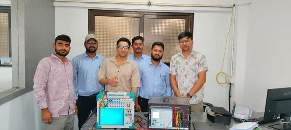
Scene (One)

3‑Phase Microcomputer Relay Protection Test Set Secondary Injection Tester For Substation Protection Relay Calibration

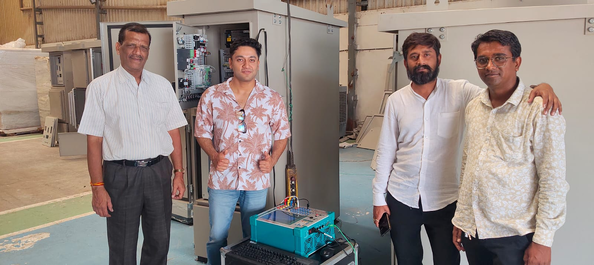
Scene (Two)
3‑Phase Microcomputer Relay Protection Test Set Secondary Injection Tester For Substation Protection Relay Calibration

Attachment Directory

Qty English Name Remarks
1 set Main unit of microcomputer relay protection test set Portable suitcase‑type mainframe
1 pc Aluminum alloy flight case For equipment storage & transport
1 pc Accessory storage bag For storing test leads
2 pcs High‑current test cable set (50A) For IA/IB/IC current output
1 pc Voltage test cable set For UA/UB/UC/UX voltage output
1 pc Binary input & output signal test wire set For binary input / binary output channel
1 pc Grounding wire For equipment safety grounding
1 pc USB data communication cable For PC software connection
1 pc AC power cord For AC220V power supply
1 bag Alligator clip terminals & spare connectors For spare replacement
1 set English user manual For operation guidance
1 set Calibration certificate Factory calibration document

Attachment Image
3‑Phase Microcomputer Relay Protection Test Set Secondary Injection Tester For Substation Protection Relay Calibration